| TAB Performance Products | |
| Installation Instructions | |
| Auto Tuner | |
Q: How does the TAB Performance Auto Tuner work? A: In simple terms the Auto Tuner works by making your bikes ECU run in a closed loop system at all times instead of just under load so that your O2 sensors can be utilized. It then takes the information from your O2 sensors and adjusts your A/F ratio so that your bike runs optimally at all times. The information the Auto Tuner gathers from your O2 sensors along with several other sensors allows it to constantly make adjustments as your riding environment changes such as elevation, temperature, etc. Q: What is the Auto Tuners target A/F ratios? A: The Auto Tuner targets a 14.5 A/F ratio when cruising for fuel economy and 13.5 A/F ratio under load for power. Q: Can I install the Auto Tuner myself? A: The TAB Performance Auto Tuner is designed to be installed at home with only a few simple tools and comes with detailed installation instructions including colored pictures as well as a link to a YouTube installation video. We tell people if you can put together a gas grill you can probably install our Auto Tuner. Q: What do I do if my motorcycle does not start after installing the Auto Tuner? A: The Auto Tuner plugs into the crank position sensor. If this signal is not making a good connection, the motorcycle will not start. Inspect the crank position sensor plug to make sure the pins are straight and not pushed out of the plug. Q: Why is the LED light on my Auto Tuner not coming on? A: Check your power and ground connection on the harness to make sure it is connected properly at the data link plug and the battery terminal. Q: What does it mean if my LED light on my Auto Tuner is not changing to green? A: When your light is not changing to green something may not be hooked up properly. After 2 minutes of running, the module will blink a code. 2 red blinks and a pause means there is no engine speed detected, check your crank position sensor plugs and make sure there is a good connection. 3 red blinks and a pause means there is no 02 sensor detected, check your 02 sensor plugs and make sure you have a good connection. Also make sure you started your bike. It can't detect an engine speed if the engine isn't running. Q: I have a 08-09 Throttle by Wire Harley Davidson Touring Model, under hard acceleration I am losing all throttle control. How do I fix this issue? A: Harley Davidson has equipped all Throttle by Wire Motorcycles with a safety feature; it is called Limp Home Mode. If there is a loss of voltage to the throttle body actuator this will cause the Limp Home Mode to occur. Always make sure that all connections are good and battery terminals are tight. If this does happen, you can pull over and cycle the key switch 4 times and it will reset the throttle body actuator. When you get to your destination go through and double check all your connections are good and tight. Also, check to see if you have any trouble codes. Q: I have a 08-09 Throttle by Wire Harley Davidson Touring Model and after installing the Auto Tuner I have lost all throttle response at start up. How do I fix this issue? A: Double check that both the power wires and the ground wire are giving power to the module. (the ground is from the throttle body actuator plug).
Q: I keep losing throttle response on my 08-09 throttle by wire, how do I fix this issue? A: The data link plug is what Harley Davidson uses to hook up their scanalizer to read trouble codes. On most Harley Davidson models the data link plug is located beside the factory ECU. On earlier Touring Models your ECU is located on the exhaust side under the side cover, early model V-Rods are under the battery. All other models, ECU is under the seat. On the 08-09 TBW Touring Models ECU is under the seat and the data link plug is located under the left side cover, under fuse panel. Q: How do I find the gray wire in the data link plug? A: When you find the data link plug, pull back the black tubing and underneath the tubing you will see wires, take the posi-tap (red and grey color) we have provided and tap into the gray wire, then tap the other end onto the red wire. Q: How do I bypass the Auto Tuner and go back to stock? A: At the throttle position sensor on your bike, unplug the Auto Tuner harness from the stock Harley-Davidson plug and re-plug the stock throttle position sensor plug back into the throttle position sensor. Your bike is now running on its original Delphi settings. Q: After installing the Auto Tuner how can I tell if the air/fuel ratio is correct? A: For the most part you can tell by how your bike is running if it's running smooth with no backfiring and your engine temperature isn't running hotter than normal then your Auto Tuner is functioning properly. You can also remove and look at your spark plugs; the porcelain should be a light tan or a dirty white color. Q: What if I am having discoloration on my spark plugs? A: If you are having discoloration on your spark plugs, install a new set of spark plugs and run the bike for a few miles and recheck the plugs to see what the plugs look like. The spark plugs should be a light tan or a dirty white color, if the spark plugs are a different color your bike may not be running at the proper A/F ratio. Q: Why am I having a high idle on my motorcycle? A: On some Harley Davidson models this will occur, we have added a secondary power wire to our harnesses that corrects this issue. If this problem still occurs, plug your throttle position sensor back to stock. When you plug your Throttle Position Sensor back to stock you are completely by passing the Auto Tuner, if it continues to idle high then you may be having problems with your bike and you will need to take your bike to a local Harley-Davidson dealer to have them check it out. Q: Why do I have two power wires on my harness? A: This is so the Auto Tuner will power up within the milliseconds that it needs to work properly. Q: Why, after installing the Auto Tuner, am I having deceleration popping and sputtering? A: The Auto Tuner relies on the 02 sensor(s) to get its readings. If there is any exhaust leaks or the 02 sensor(s) have been removed and have not been properly tightened the Auto Tuner will think that the motorcycle is running lean and add fuel, this can cause poor fuel mileage and deceleration popping and sputtering. Q: My check engine light is popping up randomly, how do I fix this issue? A: Unplug your Throttle Position Sensor and look at the pins, make sure there is not a film covering them also make sure the pins are straight. Q: How often does the Auto Tuner take reading from the O2 sensors? A: The Auto Tuner take 80 readings a second from your O2 sensors, and uses that information to constantly update it's map.Q: What if my Check Engine light is coming on and not going back off?
1. Turn ignition switch to OFF & Run/Stop switch is to Run.
P = ECM/ICM (Electronic Control Module (EFI) / (Ignition Control Module,‘Carbureted’)
6. To get the DTC within an area of diagnostics, push and hold the odometer reset button in for 5 seconds and release. If there are any DTC’s the code will be displayed or the work “none” will appear if there are no DTC’s. Push the odometer reset button again to view additional codes if they exist Below is the check engine code reference list:
B0563 Battery Voltage High TSM/TSSM Q: What if I'm havingan issue not covered above?
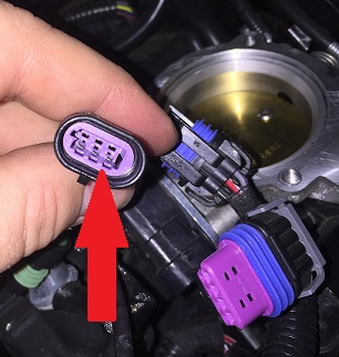
A: The most common installation issue we find is with the Throttle Position Sensor (TPS), which if not properly installed can cause a host of different issues, so this is always the best place to start. What often happens is the factory housing gets left behind when you unplug the factory connection and if you don’t have things properly lined up when you go to plug the Auto Tuner in the pins will get jammed in this housing and you won’t make a good connection. To check if this is the case pull apart the TPS connection and look on the Auto Tuner plug side to see if you see a piece of purple plastic as shown in the picture to the right. If you do fish out and remove this piece of purple plastic and discard it (you don’t need it). Then make sure the Auto Tuner pins are straight and in line with the center of the plug, and then connect
everything back together and this will most likely resolve your issue. |
|
| Exhaust | |
Q: Can I install my TAB Performance exhaust myself? A: TAB Performance exhaust systems are designed to be installed at home with only a few simple tools and comes with detailed installation instructions. Q: Do I need a fuel management system, if I'm only getting slip-ons? A: Anytime you change the exhaust system on your bike you're changing the back pressure to your engine which in turn affects your Air / Fuel Ratio or A/F causing your bike to run either rich (too much fuel) or lean (not enough fuel). If your bike is carbureted you'll need to rejet your carburetor. This should be done by a professional shop such as your Harley-Davidson Dealership. If your bike is fuel injected you'll need a fuel management system to overide your factory map settings. Q: My bike has O2 sensors do I still need a fuel management system? A: If your bike has O2 sensors then it does have some ability to make adjustments, but the factory setup was really only designed to adjust for minor changes such as differences in elevation or air temperature, not for major changes such as aftermarket exhaust. Q: What is the difference between baffled and non-baffled? A: Baffling is the part of the exhaust that provides sound supression (makes the exhaust quieter). To give you a better idea of the differences we've ranked the different options on a 1-10 scale below:
Q: Are the baffles removable? A: The baffles on most TAB Performance exhaust are removable. Unfortunately due to the design requirements, on some exhaust, the baffles are not able to be removed. Unless it specifically states on the product listing that the baffles are removable assume that they are not, or contact us if you're still unsure. Q: When I go to remove the baffles from my exhaust they only come out a few inches before becoming stuck. What can I do? A: Most likely the baffle is getting stuck on the backside of the rivets which hold the TAB Performance name plate on to the pipes. Try drilling the name plate rivets out. If it is still getting stuck it might be a piece of the rivet getting logged between the pipe and the baffle. Try pushing the baffle all the way back in and then tipping it upside down (inlet facing up), then try pulling out the baffle. Q: I bought non-baffled pipes and am now looking to quiet down the exhaust. Can I purchase the baffle seperately? A: If you purchased a non-baffled pipe unfortunately there is no way to install a baffle into the TAB Performance pipe after the fact. You can however purchase a header baffle that fits in your 3rd volume chamber (where the TAB Performance Pipes slip on), which will give you some sound suppression as well as back pressure. We have had a lot of our customers go with this option. Q: Are TAB Performance Pipes street legal? A: Although you would need to check with your governing agency to be sure, TAB Performance exhaust system are designed for racing and off-road use only and are not intended for street use. |
|
| Fuel Manager | |
Q: Can I install the Fuel Manager myself? A: The TAB Performance Fuel Manager is designed to be installed at home with only a few simple tools and comes with detailed installation instructions including colored pictures. We tell people if you can put together a gas grill you can probably install our Fuel Manager. Q: I get black smoke when I first start my bike but it goes away after it warms up. Is that normal? A: When you first start your bike there should be some black smoke that comes out of the pipes, especially when revving the engine. Once the bike warms up then the smoke should go away. This mode comes from the factory and is called a "cold start" mode which basically does the same thing as a choke. If the bike continues to smoke after warm-up and there is excess soot buildup in the pipes then it possibly is running a little too rich and you should make a tuning adjustment. Q: I need to make a fine-tuning adjustment to my Fuel Manager how do I do this? A: The way the 3 tuning pots (Low, Mid, and High) are set up is that each one controls the air/fuel mixture for a certain rpm range. The low dial controls 0-3,000 rpms, the mid dial controls 3,000-6,000 rpms, and the high controls 6,000-9,000 rpms. Basically each pot/dial can either add fuel or take away fuel within these rpm ranges. You want to try to pinpoint where you feel the bike is running rich or lean and then focus on the tuning dial that controls that range. For example if the bike had a stumble around 5,000 rpms then you would want to work on the "mid" tuning dial and either add or deduct some fuel. If you are not sure which to do then start by adding fuel and if the bike runs worse then go in the opposite direction and deduct fuel instead. Each tuning dial is set at the factory to 12 O'Clock or straight up and down and this is a zero setting or in other words no fuel added and no fuel deducted. If we want to add fuel then you would turn the dial clockwise. If you want to take away fuel or "lean" the mixture out then you will turn it counter clockwise. You will want to make small incremental steps and start by turning the pot/dial counter clockwise to about 10 or 11 O'Clock. FYI...the most that you can adjust the fuel is (+) or (-) 20%. So in other words you have the ability to add as much as 20% fuel or take away as much as 20% fuel on any of the dials/pots. After making a small 5% adjustment (1 tick mark) take the bike for a ride and see how it feels. Most bikes only need fuel added or subtracted within a small rpm range. If you make an adjustment and it actually makes the problem worse instead of better, just remember to take it back to the place where you started, 12 O'clock. We usually adjust them to the point of going just a little too far and then turn it back slightly to that perfect place. Q: Which Map setting should my Fuel Manager be set to? A: Below is a list of what bike and set of pipes each map corresponds to for each of the Fuel Manager Units.
Q: Why is my check engine light coming on and not going off? A: This means that your bike is telling you that you have a trouble code; you can go into 1. Turn ignition switch to OFF & Run/Stop switch is to Run. P = ECM/ICM (Electronic Control Module (EFI) / (Ignition Control Module,‘Carbureted’) 6. To get the DTC within an area of diagnostics, push and hold the odometer reset button in for 5 seconds and release. If there are any DTC’s the code will be displayed or the work “none” will appear if there are no DTC’s. Push the odometer reset button again to view additional codes if they exist Below is the check engine code reference list: B0563 Battery Voltage High TSM/TSSM |
|
| Hi-Flo Air Filter | |
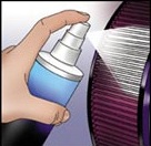
How often do I need to clean my TAB Performance Hi-Flo Air Filter? A: You should clean your Hi-Flo Air Filter every 30,000 to 50,000 miles under normal conditions. In the case of of-road or heavy dust conditions you may need to clean it more often. If your annual mileage is below 30,000 you should clean it once a year. Q: Do I need to oil my Hi-Flo Air filter before using it? A: Your TAB Performance Hi-Flo Air Filters come pre-oiled and ready to use right out of the box. However after cleaningn always make sure to re-oil your Hi-Flow Air Filter before using again. Q: How should I clean my Hi-Flo Air Filter? A: Use only approved air filter cleaning kits such as AIRAID® filter tune-up kits. Never use gasoline, detergents, solvents steam or any other non-approved method to clean your filter as it can damage your filter element. Below is a step by step process for cleaning you TAB Performance Hi-Flow Air Filter: STEP #1: Clean
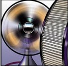
STEP #2: Dry
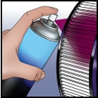
STEP #3: Re-Oil
|
|
| Will TAB Performance Products Void my Warranty | |
Q: Will installing TAB Performance aftermarket parts void my manufacturer's warranty?
A: This is a common question we get and there is a lot of misinformation out there. We're not lawyers so we can't give you legal advise but below is some information directly from the Federal Trade Commission's (FTC) website as well as a link to learn more. Will using 'aftermarket' or recycled parts void my warranty?No. An 'aftermarket' part is a part made by a company other than the vehicle manufacturer or the original equipment manufacturer. A 'recycled' part is a part that was made for and installed in a new vehicle by the manufacturer or the original equipment manufacturer, and later removed from the vehicle and made available for resale or reuse. Simply using an aftermarket or recycled part does not void your warranty. The Magnuson-Moss Warranty Act makes it illegal for companies to void your warranty or deny coverage under the warranty simply because you used an aftermarket or recycled part. The manufacturer or dealer can, however, require consumers to use select parts if those parts are provided to consumers free of charge under the warranty.
Still, if it turns out that the aftermarket or recycled part was itself defective or wasn't installed correctly, and it causes damage to another part that is covered under the warranty, the manufacturer or dealer has the right to deny coverage for that part and charge you for any repairs. The FTC says the manufacturer or dealer must show that the aftermarket or recycled part caused the need for repairs before denying warranty coverage.
|
|